Skip to content
AUTOMOTIVE & ERGONOMIC METROLOGY[email protected]
PFS///PEDAL FORCESENSOR SYSTEMSRequest Quote / CAD ↗

PFS / ENGINEERING SELECTION

Pedal Force Sensor Selection

Find a configuration request by measurement task, compare up to three models and carry your preferred interface into an engineering RFQ.

19 CONFIGURATION REQUEST MODELS

Start with the measurement task.

Ranges and interfaces below define an engineering request. Exact supplied ratings, pinouts and compatible electronics follow the approved configuration.

19 matching request models

Task changes reset the filters below. Reset filters restores all request models and keeps your comparison; Clear comparison removes the shortlist.

0 / 3 comparison slots selectedView comparison ↓
Range groups use the catalog nominal request value; multi-axis rows use the largest nominal Fz. Custom ranges and combined-load limits require separate review.
ShortlistRequest codeForce / travel selectionApplication / architectureRequested interfaceEngineering handoff
PFS-220-500N500 N / 112.4 lbfAutomotive brake / brake robot
Bridge sensor
mV/V bridge / 0–5V / 0–10V conditioning / CAN integration / USB acquisitionConfigure this model →
PFS-220-1000N1,000 N / 224.8 lbfAutomotive brake / brake robot
Bridge sensor
mV/V bridge / 0–5V / 0–10V conditioning / CAN integration / USB acquisitionConfigure this model →
PFS-220-1500N1,500 N / 337.2 lbfAutomotive brake / brake robot
Bridge sensor
mV/V bridge / 0–5V / 0–10V conditioning / CAN integration / USB acquisitionConfigure this model →
PFS-220-2500N2,500 N / 562.0 lbfAutomotive brake / brake robot
Bridge sensor
mV/V bridge / 0–5V / 0–10V conditioning / CAN integration / USB acquisitionConfigure this model →
PFS-200-100N100 N / 22.5 lbfClutch / accelerator / industrial foot pedal
Bridge sensor
mV/V bridge / 0–5V / 0–10V conditioning / CAN integration / USB acquisitionConfigure this model →
PFS-200-250N250 N / 56.2 lbfClutch / accelerator / industrial foot pedal
Bridge sensor
mV/V bridge / 0–5V / 0–10V conditioning / CAN integration / USB acquisitionConfigure this model →
PFS-200-500N500 N / 112.4 lbfClutch / accelerator / industrial foot pedal
Bridge sensor
mV/V bridge / 0–5V / 0–10V conditioning / CAN integration / USB acquisitionConfigure this model →
PFS-200-1000N1,000 N / 224.8 lbfClutch / accelerator / industrial foot pedal
Bridge sensor
mV/V bridge / 0–5V / 0–10V conditioning / CAN integration / USB acquisitionConfigure this model →
PFS-KIT-1500NForce 0–1,500 N; travel 0–200 mmBrake-by-wire / pedal feel
Portable force + travel kit
0–5V / 0–10V conditioning / CAN integration / USB acquisitionConfigure this model →
PFS-KIT-CANForce 0–1,500 N; travel 0–200 mmBrake-by-wire / pedal feel
Force + travel, CAN integration request
CAN integrationConfigure this model →
PFS-KIT-USBForce 0–1,500 N; travel 0–200 mmBrake-by-wire / pedal feel
Force + travel, USB logging request
USB acquisitionConfigure this model →
PFS-3AX-BIKEFz 1,000–2,000 N; Fx / Fy ±500 NBicycle biomechanics
Three-axis configuration
mV/V bridge / 0–5V / 0–10V conditioning / CAN integration / USB acquisitionConfigure this model →
PFS-3AX-RUDDERFz 1,000–2,000 N; Fx / Fy ±500 NAircraft rudder / toe-brake ergonomics
Three-axis configuration
mV/V bridge / 0–5V / 0–10V conditioning / CAN integration / USB acquisitionConfigure this model →
PFS-2AX-PEDALFz 1,000 N; Fy ±500 NVehicle / cockpit ergonomics
Two-axis configuration
mV/V bridge / 0–5V / 0–10V conditioning / CAN integration / USB acquisitionConfigure this model →
PFS-SIM-100KG100 kgf / 980.67 NF1 / GT simulator OEM
Hydraulic / elastomer integration
mV/V bridge / 0–5V / 0–10V conditioning / USB acquisitionConfigure this model →
PFS-SIM-150KG150 kgf / 1,471.00 NF1 / GT simulator OEM
Hydraulic / elastomer integration
mV/V bridge / 0–5V / 0–10V conditioning / USB acquisitionConfigure this model →
PFS-SIM-200KG200 kgf / 1,961.33 NF1 / GT simulator OEM
Hydraulic / elastomer integration
mV/V bridge / 0–5V / 0–10V conditioning / USB acquisitionConfigure this model →
PFS-HB-1000N500 / 1,000 N requested rangeHandbrake operating force
Articulated lever fixture
mV/V bridge / 0–5V / 0–10V conditioning / CAN integration / USB acquisitionConfigure this model →
PFS-GS-500N500 N nominal; 100–1,000 N custom reviewGear-shift push / pull force
Shift-knob fixture
mV/V bridge / 0–5V / 0–10V conditioning / CAN integration / USB acquisitionConfigure this model →

YOUR ENGINEERING SHORTLIST

Compare up to three request codes.

0 / 3 selected

Keep units, force directions and acquisition scope together. These are configuration requests; supplied performance and compatibility require written review. Your shortlist follows client navigation in this tab. Share model codes to restore it after a reload. Share links do not save contact details, notes or the primary model configuration.

Back to task filters ↑

Select Compare in the model table. You can shortlist models from different tasks; no winner or safe capacity is calculated.

FROM REQUEST CODE TO A REVIEWABLE TEST SETUP

Compare the force path before comparing the model number.

The directory narrows configuration requests by measurement task and catalog labels. It does not infer a safe operating range from a peak force. Use the shortlist to expose missing information before a quotation or drawing release.

Tasks are starting views of the catalog. You can compare across tasks when the same project needs a single force channel, force + travel or independent force components.

Review all nine measurement-task checklists

Brake effort / brake robot

PFS-220-500N · PFS-220-1000N · PFS-220-1500N · PFS-220-2500N

  • Pedal envelope, contact point and installed stack height
  • Expected force-time history and off-axis load direction
  • Readout input range and installed calibration scope

Clutch, accelerator / industrial foot pedal

PFS-200-100N · PFS-200-250N · PFS-200-500N · PFS-200-1000N

  • Minimum useful force and pedal return behavior
  • Allowed added mass, cable routing and full travel
  • Duty cycle, temperature and repeatability requirement

Pedal feel / synchronized force + travel

PFS-KIT-1500N · PFS-KIT-CAN · PFS-KIT-USB

  • Travel reference point and draw-wire anchor geometry
  • Common timebase, sample rate, filtering and channel latency
  • Portable power, trigger and raw data export requirements

Bicycle force components

PFS-3AX-BIKE

  • Pedal coordinates, sign convention and crank interface
  • Separate crank angle / cadence inputs if power is required
  • Combined loading and cross-axis calibration scope

Rudder / toe-brake ground testing

PFS-3AX-RUDDER

  • Left / right fixture layout and coordinate directions
  • Rudder and toe-brake force channels required by the test
  • Combined loads and acquisition / calibration scope

Two-axis Fy / Fz pedal ergonomics

PFS-2AX-PEDAL

  • Fy / Fz ranges and sign convention
  • How unmeasured Fx is controlled or documented
  • Combined loading, fixture alignment and calibration matrix

F1 / GT simulator OEM

PFS-SIM-100KG · PFS-SIM-150KG · PFS-SIM-200KG

  • Whether the stated force is at the sensor or driver foot pad
  • Lever geometry, compliant element and stop arrangement
  • Controller input, excitation, pinout and USB HID review

Handbrake operating effort

PFS-HB-1000N

  • Grip point, pull direction and lever geometry
  • Fixture interface and allowed added mass
  • Installed calibration and acquisition requirements

Gear-shift push / pull effort

PFS-GS-500N

  • Single-axis push / pull direction and nominal range
  • Knob thread, adapter envelope and allowed added mass
  • Cable restraint and installed calibration scope

1. Define the force reference.

State where force acts, in which direction, and whether the value refers to the sensing element, driver foot pad or lever grip. For a simulator mechanism, bring the pivot and load-path geometry. A sensor-force request cannot establish driver force by itself.

2. Name every measured quantity.

One force direction with push and pull signs remains one force channel. Fy/Fz and Fx/Fy/Fz require the corresponding independent channels. Force + travel adds a displacement quantity with its own reference point and synchronized acquisition.

3. Carry the review scope into the RFQ.

Choose one request code to prefill the form, then refine the output, fixture, connector and calibration needs. Copy or export the comparison for purchasing review. Final supplied specifications, evidence, price and delivery belong in the written quotation.

Three reproducible directory examples. These demonstrate software filtering, not measured hardware suitability.
Measurement taskDirectory resultInformation still required
Pedal feel with USB loggingForce + travel task, USB interface → PFS-KIT-1500N and PFS-KIT-USBTravel reference, synchronized sample rate, latency, power and export format
Gear-shift push / pullShift task → PFS-GS-500N; one force channelForce direction, knob / adapter drawing, fixture mass and installed calibration
SIM project asking for CANSIM + CAN → no catalog request matchReset the interface filter to review bridge / analog / USB requests, or ask for a custom integration review

CAPACITY / UNITS / LOAD HISTORY

Keep N, lbf and kgf attached to every force value.

NIST lists approximately 4.448222 N per lbf and 9.80665 N per kgf. A 500 lbf original part is approximately 2,224 N, rather than a 500 N request. The comparison keeps each catalog's units in its nominal-selection row.

A nominal range is only one input. Supply the expected time history, off-axis loading, minimum useful force and uncertainty requirement. A claimed overload percentage or a larger catalog value does not establish an approved impact, fatigue or combined-load envelope.

NIST force-conversion reference ↗

Write the reference beside the number.

01Force at the sensing element, foot pad or grip

02Nominal range, expected time history and minimum useful force

03Axis direction, signs and simultaneous loads

04Required uncertainty and acceptance evidence

MOUNTING / ACQUISITION / CALIBRATION

Resolve the installed interfaces before procurement release.

Fit includes the original pedal and fixture.

Provide pedal width, curvature, clearance, mounting restraint and cable routing, or the simulator / cockpit adapter drawing. The original Michigan Scientific BPFT3 has a specific pedal-pad removal and retaining arrangement. Matching capacity or a similar silhouette does not establish the same installation.

Original BPFT3 mounting description ↗

Define the readout input and output.

Keep passive bridge input, conditioned voltage, CAN integration and USB/controller requests distinct. Supply excitation or power, input range, channel count, connector view, pinout and the required message or software interface. For multiple channels, document synchronization and latency.

Readout and acquisition review →

Separate planning files from issued records.

The public PDFs are configuration briefs; the blank calibration worksheet helps define a test scope. Ask for the released drawing revision, supplied sensor/readout identification, traceability, uncertainty and relevant acceptance results. Fixture and electronics costs are quotation-specific.

Drawing and calibration evidence status →

MODEL SELECTION / ENGINEERING ANSWERS

Resolve the request scope before choosing a configuration.

How does the task selector choose request models?

It maps your measurement task to existing catalog request codes, then applies your family, nominal-range and interface filters. It does not calculate a safe capacity, select an overload margin or approve supplied hardware.

Can I compare 500 N and 500 lbf as the same range?

No. N, lbf and kgf are different force units. 500 lbf is approximately 2,224 N; retain units when comparing requests and original manufacturer parts.

Does a 200 kgf SIM sensor imply 200 kgf at the foot pad?

The catalog value is a sensor-force request. Driver force depends on the installed lever geometry and load path; provide the mechanism for review before selecting an OEM range.

When should I request force and travel together?

Use a force + travel request when you need a force-versus-displacement trace for pedal feel, stiffness intervals or loading/unloading behavior. Define the travel reference and synchronized acquisition requirements.

Does push / pull mean a three-axis sensor?

A push/pull shift fixture can measure one force direction in two signs. PFS-GS-500N is a single-axis request; independent Fy/Fz or Fx/Fy/Fz components use the corresponding PFS-3AX family request.

What does a downloaded comparison establish?

It records the chosen configuration requests and their review scope. Supplied drawings, capacity-specific performance, calibration, compatible electronics, price and delivery still require written confirmation.

Browse all six sensor families
01PFS-220
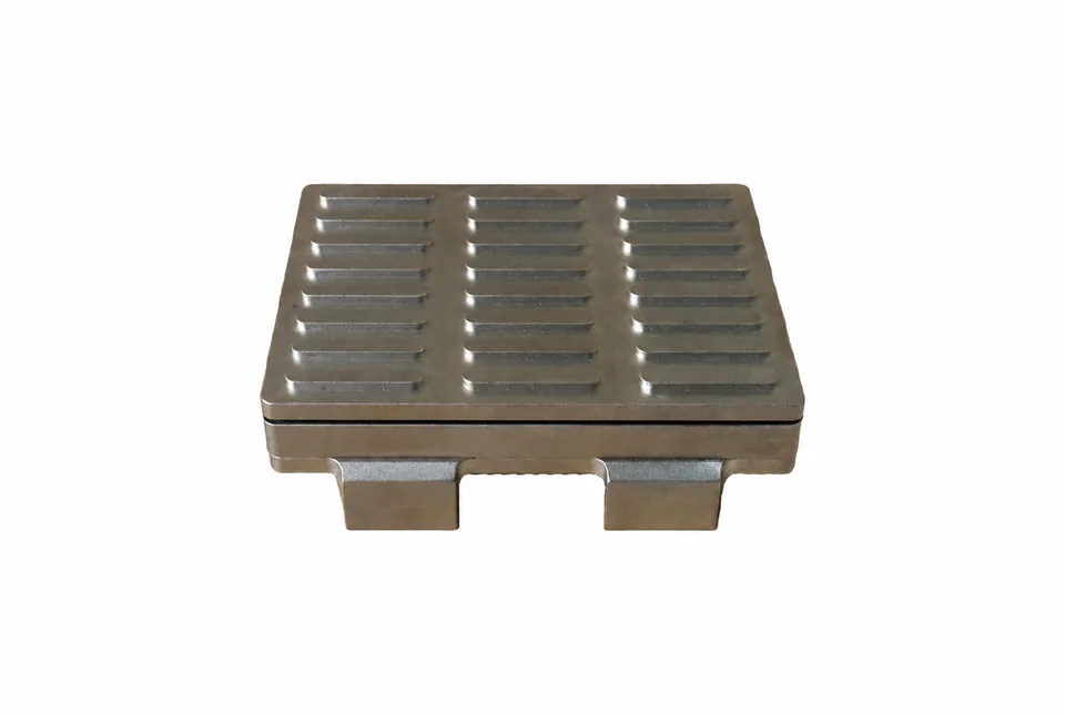
Silver rectangular pedal force sensor three columns of transverse grip grooves two lower mounting tabs; supplier reference photo
Pedal contact sensorSupplier component reference

AUTOMOTIVE / BRAKE VALIDATION

Brake Pedal Force Sensors

Measure driver brake effort with a low-profile, quick-mount pedal force load cell. Specify the pedal envelope, peak load and readout before selecting a road-test configuration.

500 / 1,000 / 1,500 / 2,500 N
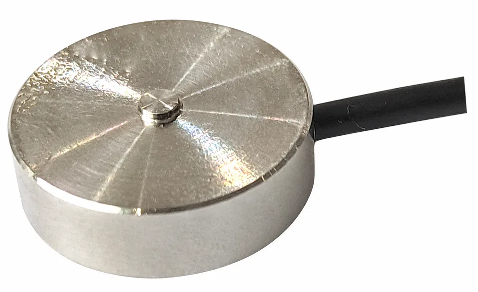
02PFS-200
Silver low profile disc compression force sensor central nub black cable top oblique; supplier reference photo
Compact compression elementSupplier component reference

LOW PROFILE / LOW FORCE

Clutch, Accelerator & Foot Pedal Load Cells

Capture clutch effort, accelerator resistance and industrial foot-pedal actuation without overlooking sensor weight, cable drag or the return mechanism.

100 / 250 / 500 / 1,000 N
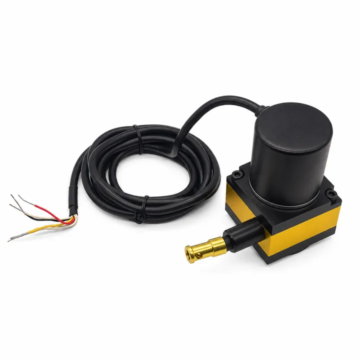
03PFS-KIT
Yellow black draw wire displacement sensor vertical cylinder coiled cable colored flying leads; supplier reference photo
Draw-wire travel referenceSupplier component reference

SYNCHRONIZED / FORCE VS TRAVEL

Pedal Force + Travel Test Kits

Record pedal force and pedal displacement on a common timebase to compare stiffness, free play and loading/unloading behavior.

Force 0–1,500 N; travel 0–200 mm
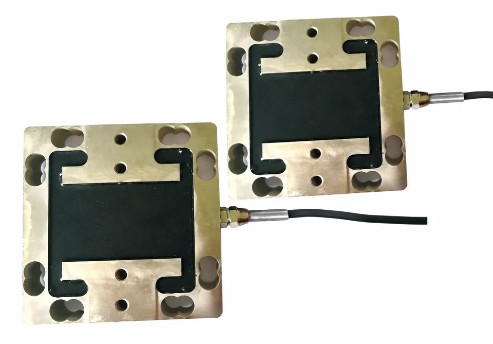
04PFS-3AX
Gold tone square three component force sensor staggered pair black central flexure right cables; supplier reference photo
Multi-axis force elementSupplier component reference

FX / FY / FZ • HUMAN FACTORS

3-Axis Pedal & Bicycle Force Sensors

Separate vertical pedal force from fore-aft and lateral components for cockpit ergonomics and laboratory bicycle pedal-force analysis.

Fz 1,000–2,000 N; Fx / Fy 500 N
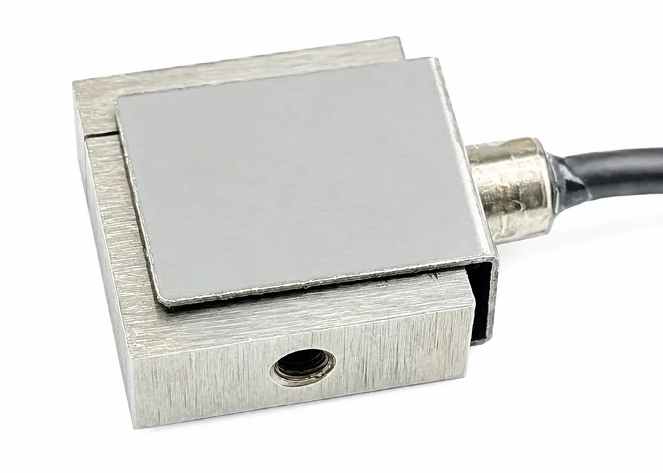
05PFS-SIM
Silver miniature s beam load cell protected flexure slot bottom threaded hole right black cable; supplier reference photo
Pedal load-path componentSupplier component reference

OEM / DRIVER TRAINING

F1 & Pro Sim Racing Brake Load Cells

Specify a stiff force-sensing module for hydraulic or elastomer brake pedals, matched to your pedal ratio and controller.

100 / 150 / 200 kgf nominal
06PFS-COCKPIT
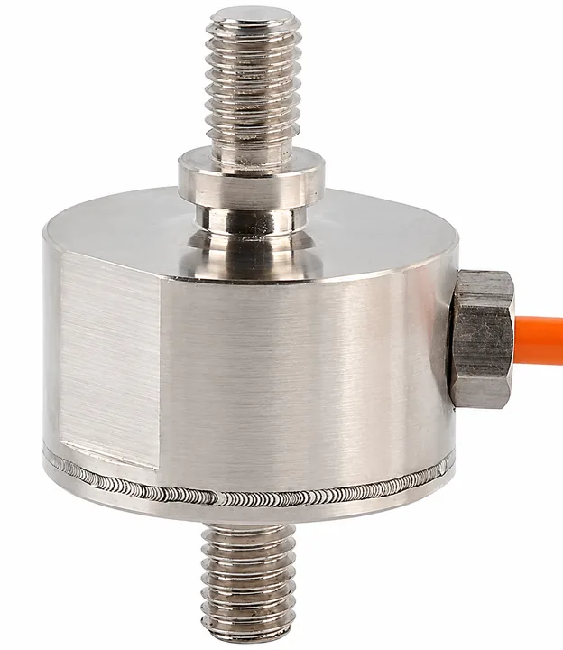
Silver inline cylinder load cell opposed threaded studs right gland orange cable upright; supplier reference photo
Inline force elementSupplier component reference

COCKPIT / OPERATING EFFORT

Handbrake & Gear-Shift Force Sensors

Request articulated handbrake and gear-shift force fixtures for vehicle ergonomics and cockpit test programs.

Handbrake 500–1,000 N; shift 100–1,000 N review

ENGINEERING / REQUEST

Build the right
measurement chain.

Send your force range, pedal dimensions and acquisition requirements. Request a mounting drawing, CAD review and a complete sensor / readout quotation.

Replacing an existing sensor?

Include the exact part number, drawing revision, connector pinout and calibration requirements. Compatibility is reviewed per configuration.

Corporate procurement requests

Include your purchasing entity, PO requirements, destination and required invoice / calibration documents. Payment options, trade terms, freight and delivery are confirmed in the written quotation.
MODEL-AWARE ENGINEERING REQUEST

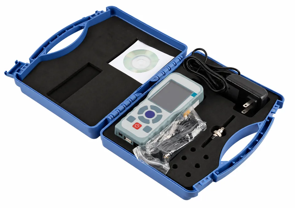
Primary model: PFS-220-1500N1,500 N / 337.2 lbf · Automotive brake / brake robotHandheld peak-hold meter · mV/V bridgeQuick-release pedal plate / strap-clamp request

Start with your model, contact and delivery needs. Connection and acquisition details can be refined below; supplied specifications require written review.

Optional connector, acquisition & calibration details

These current values are included in your copied, emailed and submitted request, even when this panel is closed. Change them if your integration needs differ.

Accessory planning allowances

Selected allowance: $260. A travel logger replaces the separate handheld meter in this request. Sensor, custom fixtures, USB / HID electronics, accredited calibration, taxes and shipping are quoted separately. Actual hardware compatibility and any kit-included mounting are reconciled in the quotation.

We use these details to respond to your request. Privacy policy. Request codes and design targets require written confirmation.

Preview the text sent with this request
Target model / competitor to replace: PFS-220-1500N
Force capacity & application: 1,500 N / 337.2 lbf; Automotive brake / brake robot
Signal / readout bundle: Handheld peak-hold meter; mV/V bridge
Connector / cable: Flying leads — pinout review; 4.5 m requested
Quantity / destination: [please specify]; [please specify]

Additional engineering requirements:
Target delivery: [please specify]
Mounting scope: Quick-release pedal plate / strap-clamp request
Trigger: No trigger requested
Sampling / bandwidth request: To be recommended
Calibration request: Five loaded points + zero; scope to confirm
Accessories: Quick-release plate & strap / clamp request (+$45 planning allowance); Battery handheld meter: peak hold, tare & USB logging (+$215 planning allowance)
Accessory planning allowance: $260 (sensor, custom fixtures, USB/HID electronics, accredited calibration, tax and freight excluded)
Contact: [please specify] | [please specify] | [please specify]
Project notes: [please specify]

Please confirm the approved drawing, configured outputs, calibration scope, price and delivery in your quotation.