Handheld effort meter
Battery power, tare, engineering-unit display and peak hold. Confirm capture bandwidth, update rate, bridge excitation and export function.
READOUT / IN-VEHICLE DAQ
Choose a handheld pedal force meter for peak effort, a logger for waveforms or synchronized channels for force and displacement.
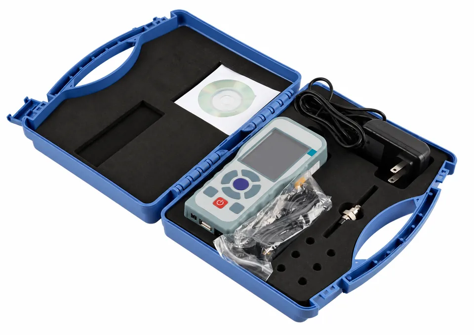
Battery power, tare, engineering-unit display and peak hold. Confirm capture bandwidth, update rate, bridge excitation and export function.
Specify sample rate, timestamps, filters, trigger and file format. For CAN 2.0B / J1939, request the actual message map or DBC, IDs, bit rate and scaling. Protocol availability is configuration-specific.
Require a common timebase, defined channel latency and installed travel calibration. Specify 0–200 mm travel, suitable anchors and data export.
Peak hold answers the maximum captured force within the instrument’s bandwidth. A force–travel curve needs paired force and displacement samples with known timing, reference positions and filtering.
Secure cables and the display so they do not obstruct pedal movement or the driver. Confirm vehicle supply compatibility, battery runtime and the test team’s installation procedure.
View force + travel kits ↗FORCE VS TRAVEL / ILLUSTRATIVE
REVIEWED SUPPLIER REFERENCES
Product and component references for configuration review. Confirm the supplied geometry, mounting and electronics in the approved drawing.
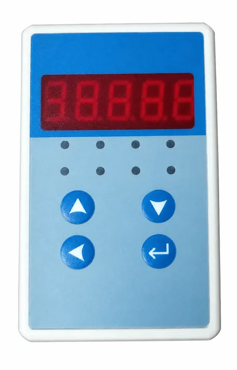
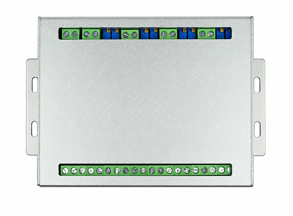
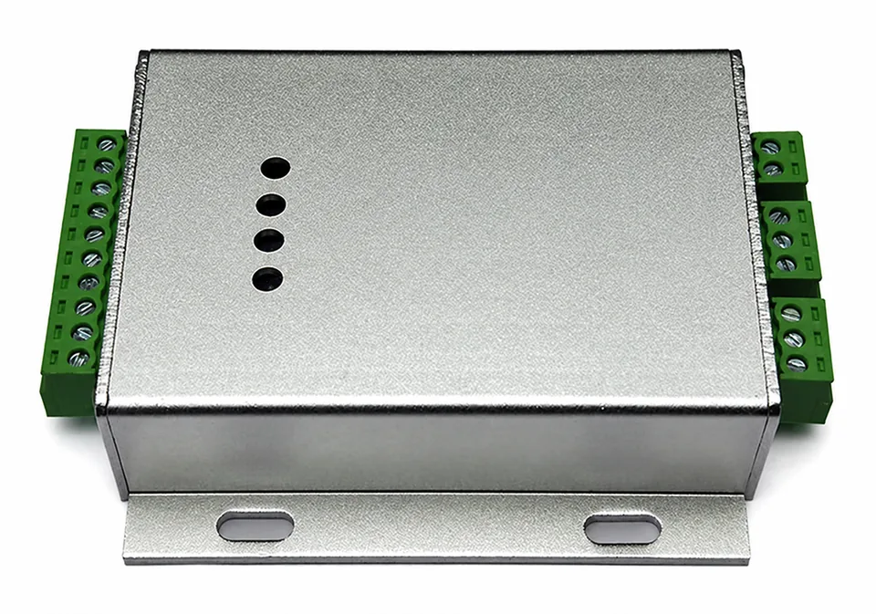
TWO CHANNELS / ONE TIMEBASE
mV/V bridge → excitation / conditioner
Travel sensorInstalled displacement → calibrated channel
Common clock, channel latency, filter and trigger definition
Timestamp, force_N, travel_mm, load / unload branch and test reference
Request sample rate per channel, effective bandwidth and timing error separately. A fast screen refresh or peak-hold function does not establish synchronized acquisition.
BRAKE TRIGGER / EVENT MARKER
Request a 5 N threshold or specify your own. Confirm activation / release hysteresis, edge polarity, logic level, output current, input isolation, debounce and propagation delay. A trigger timestamps a chosen threshold; it is not automatically identical to first foot contact or the start event in every test procedure.
The original Racelogic RLACS292 interface illustrates a separate event-marker architecture. It does not establish a validated PFS trigger specification.
For CAN 2.0B / J1939 include bit rate, IDs / PGNs, scaling, units, timestamps and DBC / message-map requirements. For analog include input range, impedance and common reference. For USB / HID include OS, controller and export expectations.
CONTINUE YOUR SELECTION
ENGINEERING / REQUEST
Send your force range, pedal dimensions and acquisition requirements. Request a mounting drawing, CAD review and a complete sensor / readout quotation.
Include the exact part number, drawing revision, connector pinout and calibration requirements. Compatibility is reviewed per configuration.
Include your purchasing entity, PO requirements, destination and required invoice / calibration documents. Payment options, trade terms, freight and delivery are confirmed in the written quotation.