LOCAL CSV REVIEW / N + mm
Pedal Force–Travel CSV Viewer
Inspect paired force/displacement rows and two selected points. The file stays in this page's memory; the tool does not upload or store it. Maximum 1 MiB / 5,000 data rows.
Paste CSV instead
Use signed N and mm with decimal points. Extra columns are ignored, including timestamps and branch labels. Each row must already pair the channels correctly; no timing correction is applied.
No curve loaded. Open a CSV, paste text, or load the clearly labeled synthetic example. Invalid input removes the previous result.
CSV FORMAT / INTERPRETATION
Preserve the pair, the order and the units.
Export one already paired force/displacement recording. Use N and mm before importing; a load-cell voltage or a draw-wire voltage requires its own approved conversion.
travel_mm,force_N,data_type
0,0,SYNTHETIC_NOT_MEASURED
20,100,SYNTHETIC_NOT_MEASURED
40,300,SYNTHETIC_NOT_MEASURED
This three-row example is invented software input, not a physical pedal measurement. Choosing rows 2 and 3 gives (300 − 100) / (40 − 20) = 10 N/mm.
The reader supports quoted commas and escaped quotes as described by RFC 4180. This application's required headers, numeric bounds, blank-line handling and UTF-8 requirement are its own import rules.
| Review question | Viewer behavior | Engineering follow-up |
|---|---|---|
| Which values appear on the trace? | Every accepted paired row, in file order; signs retained. | Separate cycles or branches in the original export if needed. |
| What happens to a bad force cell? | The entire new import is rejected, with a data row number. | Correct missing / nonnumeric cells; no bad rows are silently dropped. |
| Does a negative slope mean failure? | It reports the signed two-point ratio only. | Check branch, direction, coordinates and the applicable test plan. |
| What if the two travels match? | No slope is reported. | Choose two different travel coordinates within the intended interval. |
A paired row is not proof of simultaneous sampling.
NI's CompactDAQ timing explanation distinguishes a shared task clock from channels scanned in succession on a multiplexed module. The practical implication for this viewer is that a CSV's paired columns alone cannot establish their timing. Ask for the acquisition configuration and channel delay evidence; this tool does not establish PFS logger performance.
Before discussing a trace, retain the original file, sensor/readout identification, calibration scope, load direction, displacement reference, sample/filter settings, branch and selected rows. The summary is a review aid; sensor capacity and hardware compatibility require a separate configuration review.
Before using a force–travel trace in an RFQ.
Which CSV columns and units does the viewer accept?
Use unique headers travel_mm and force_N with signed decimal or scientific-notation numbers. The comma-separated UTF-8 file may contain extra columns, quoted fields and LF or CRLF line endings. Blank lines are ignored. Each nonblank data record must have the same field count as the header. Limits are 1 MiB, 5,000 data rows and absolute coordinate values of 1e9. No units or decimal separators are guessed.
Does pairing force and travel in a CSV prove synchronization?
No. The viewer assumes each row is already a correctly paired sample. It ignores timestamps, does not correct channel delays and does not interpolate channels. Confirm acquisition clocks, channel skew, filters, displacement geometry, calibration and the travel zero before interpreting the curve.
Is the two-point slope the pedal stiffness?
It is only the signed ratio of force change to travel change between your selected rows. It is not a fitted tangent, an average over all intermediate rows, a free-play detector or a hysteresis-energy calculation. A loading-to-unloading pair or a near-zero travel difference can be misleading. Choose a documented branch and interval.
What data goes into an engineering inquiry?
Opening a file does not upload or store it. Copy and download contain only the displayed numeric summary, selected rows and limitations. Append summary to RFQ notes is an explicit action that preserves existing notes and the configured model; the usual RFQ submission then sends those notes. The full CSV and filenames are not included; selected row coordinates and numeric ranges are included in the summary. Clearing the viewer does not remove a summary already appended to the RFQ.
REVIEWED SUPPLIER REFERENCES
Separate the force, travel and readout roles.
Product and component references for configuration review. Confirm the supplied geometry, mounting and electronics in the approved drawing.
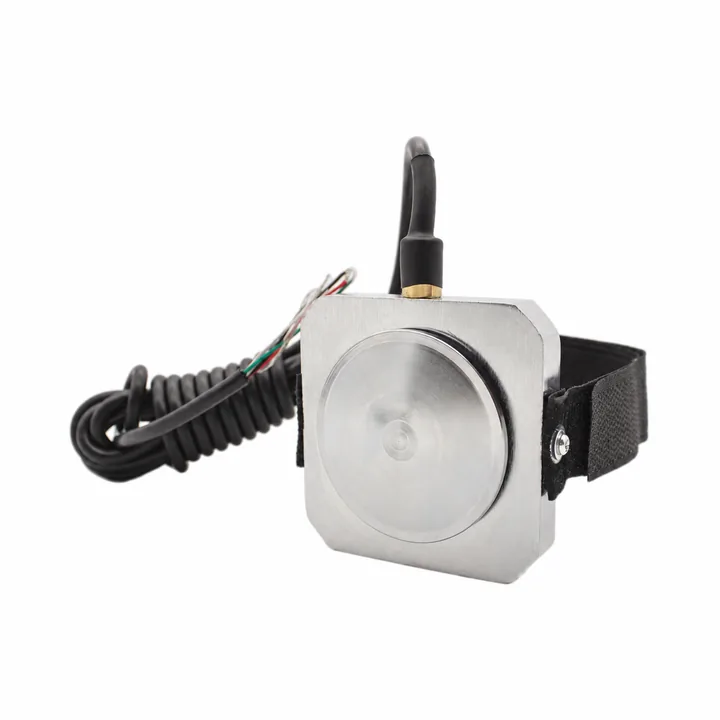
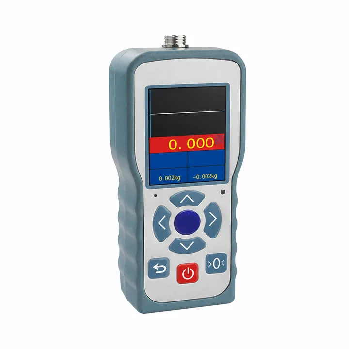
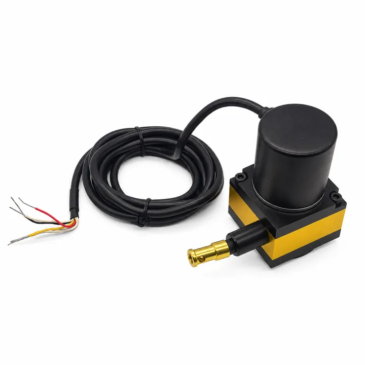
Which document applies to the test?
Pedal force is one channel in a brake test. Use the applicable procedure and revision to define vehicle setup, instrumentation and acceptance criteria.
| Reference | Test context | What to confirm |
|---|---|---|
| SAE J2909 | Light-vehicle dry and wet stopping-distance test procedure | Applicable revision, channels, calibration and full vehicle test plan |
| UN Regulation No. 13-H | Passenger-car braking type-approval requirements | Applicable amendment series, vehicle category and approval procedure |
| ISO 7975 | Passenger-car braking in a turn, open-loop test method | Test conditions, steering / braking inputs and vehicle response channels |
| FMVSS 135 | Light-vehicle brake-system requirements in 49 CFR 571.135 | Current regulatory text, applicability and complete compliance evidence |
This overview does not reproduce test limits or replace the current documents. A sensor is not independently “certified to” a vehicle brake procedure merely because it measures pedal effort.
UNITS / INTERVAL STIFFNESS
Force is not pressure.
kgf is not kg.
Use N or lbf for pedal effort. One kgf equals 9.80665 N; kg is a mass unit. Hydraulic pressure requires its own pressure sensor and cannot be inferred from foot force without the full mechanical and hydraulic model.
For an ideal lever, pushrod force = foot force × pedal ratio, with the ratio defined by perpendicular moment arms. Booster action, friction and changing geometry must be handled separately.
Force conversion & interval stiffness
1 lbf = 4.4482216153 N. Average stiffness = ΔF / Δx for the chosen interval; no stopping-distance or vehicle-compliance conclusion follows.
Ideal pedal lever ratio
Uses ΔF from the force-change input: ΔFfoot × a = ΔFpushrod × b at a fixed pedal position. These are perpendicular moment arms at the chosen pedal position, not simply arbitrary link lengths. Booster action, friction, deflection and changing angles are excluded.
Why measure pedal free play?
Initial travel can occur before substantial load builds. Recording force against a defined travel reference helps distinguish clearance, compliance and the later stiffness region.
Compare loading and unloading to assess hysteresis. Estimate stiffness over stated intervals; a single force divided by total travel can hide dead travel and nonlinear behavior.
Draw-wire extension depends on its mounting geometry. Validate the displacement channel through the operating arc, then synchronize it with force.
FORCE VS TRAVEL / ILLUSTRATIVE
Sources for your test plan
- SAE J2909 official standards record
- ISO 7975:2019 official record
- UNECE vehicle regulations: Regulation 13-H
- eCFR: 49 CFR 571.135
Reviewed 2 November 2026. Check the currently applicable edition and amendment series with your test authority.
SOFTWARE EXAMPLE / NOT HARDWARE DATA
Try a reproducible force–travel CSV.
The example uses 2 mm steps from 0 to 120 mm and back, with a 0.02 s step interval. Loading force is max(0, (travel_mm − 10) × 8) N; unloading uses 0.85 times that value. The shape is deliberately synthetic and has not been measured on a PFS sensor or vehicle.
Download synthetic curve (CSV) ↓Use it to check CSV import, axes and plotting. It does not establish actual free play, stiffness, sampling performance or brake feel.
Make a complete test request.
- Identify the applicable vehicle category, procedure and revision; do not transfer one test’s force / travel limits to all vehicles.
- Define force capacity, minimum useful force, off-axis loads, reference point and permitted added height / mass.
- Specify synchronized force / displacement channels, trigger threshold, effective bandwidth, timing and environmental conditions.
- Agree on calibration, uncertainty, fixtures and acceptance evidence before releasing the measurement system.
CONTINUE YOUR SELECTION
From pedal load to usable data.
ENGINEERING / REQUEST
Build the right
measurement chain.
Send your force range, pedal dimensions and acquisition requirements. Request a mounting drawing, CAD review and a complete sensor / readout quotation.
Include the exact part number, drawing revision, connector pinout and calibration requirements. Compatibility is reviewed per configuration.
Include your purchasing entity, PO requirements, destination and required invoice / calibration documents. Payment options, trade terms, freight and delivery are confirmed in the written quotation.